The spread of automation across many industries has led to the deployment of imaging systems in more environments than ever, many of which contain harsh or extreme conditions. Machine vision relies on imaging lenses to sense application environment, to sort items, guide navigation systems, make accurate measurements, and much more. While standard design imaging lenses typically provide the user with a wider range of operating specifications to choose from than custom ruggedized lenses, standard lenses often fail in extreme or harsh environments which contain shock and vibration, intrusive dust or liquid, and extreme or changing temperatures.
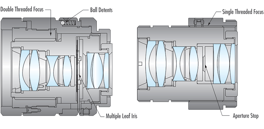
Industrial ruggedized lenses are designed and manufactured with as few moving parts as possible in order to withstand shock and vibration. For example, standard imaging lenses typically feature an adjustable iris composed of thin metal leaves with ball detents and are used to adjust the overall light throughput in the system by changing the f-number and size of the aperture. Repeated movement of the dynamic mechanics from shock and variation, however small in scale, can cause damage over time and result in part failure. For industrial ruggedized imaging lenses, this iris is replaced with a fixed aperture stop.
While shock and vibration may destroy standard imaging lenses, and industrial ruggedized imaging lenses can withstand these effects, imaging systems that rely on highly accurate, repeatable performance and must maintain sensor calibration may fail in particularly high shock and vibration environments. This is because the lens elements that sit within the inner bore of the barrel of an imaging lens assembly are surrounded by a bore gap of around 10 microns, between the outer diameter of the lens and the inner diameter of the barrel. Though this bore gap is very small, the effects of tip, tilt, and decenter from only a few microns can sum to reduce the optical pointing stability of the lens. Lower optical pointing stability usually results in significant amounts of pixel shift.
Stability ruggedized imaging lenses, like industrial ruggedized imaging lenses, also feature as few complex moving components as possible, but the optical elements within have been glued to the barrel to maintain optical pointing stability and minimize pixel shift.
Ingress protection (IP) ruggedization seals off the internal optical components from liquid and debris intrusion. Movable internal components are extremely susceptible to damage from moisture and solid intrusion. As such, IP lens designs feature the same design reductions as industrial ruggedized lenses. Protection from intrusion is in the form of O-rings and RTV silicone applied to susceptible points within the assembly. In addition, many IP lenses feature hydrophobically coated windows and/or lens elements.
IP is available in varying options and degrees of protection. Products with IP are given ratings which correspond to the these. IEC 60529 is the international standard that provides the test conditions for each rating. An IP rating is specified with two characters. The first character tells the user if the product has been tested against solids intrusion and to what degree.
The second character tells the user if the product has been tested for intrusion against liquids.
Managing the thermal effects of an optical design must be done at early stages in the design process as adjusting the temperature of the application environment may not be possible. All matter expands or contracts related to the coefficient of thermal expansion and the refractive index of transmissive materials changes related to the temperature coefficient of refractive index as temperature changes. These properties are empirically determined and reported by material manufacturers. Over narrow temperature ranges and for most standard performance imaging systems, these thermal effects often are negligible. However, for environments with extremely hot, cold, or variable temperatures, for example, space-grade equipment, or for extremely high-performance imaging systems, specially designed athermal imaging lenses are needed.
Athermalized designs fall into two categories. The first is called active athermalization in which lenses are designed to withstand environmental temperatures and not become critically damaged, though the lens may not perform at optimal or even nominal specifications. This type of athermalization may require manual adjustments to focus to find the optimal operating condition.
The second type is passive athermalization, which requires no additional adjusting or compensation for the temperature over the specified working temperature range. The passive athermalization of imaging lenses has long been modeled in raytracing software used in lens design. The simulation has been rather reliable for predicting the focus change and modulation transfer function (MTF) performance, and for a long time was the standard used for verifying the performance over temperature.
In recent years, applications particularly in the automotive industry have pressed the need for tested performance. This has expanded the use of MTF testing over temperature. Testing MTF at temperature is a complex task but has slowly become an available option for validating simulations in raytracing. For actively athermalized lenses where survivability is of greater concern than MTF performance over temperature, simulations have typically been very difficult. However, testing is simple, and it has long been the case that parts get validated by thermal cycling and inspecting for damage. Because of the very tight fits used in many high-performance imaging lenses, cold temperatures can be a real concern for potential damage, as the metal barrels will shrink faster than the glass optics, causing them to compress and possibly fracture.
Ruggedization options for imaging lenses are as numerous as the applications for which they are used. As automation continues to improve, imaging systems will continue to be integrated into harsh or extreme application environments. As such, advances in ruggedization technologies are extremely important and have never been more relevant. The environmental conditions of the application will not only dictate exactly what performance specifications are needed, but also which types of ruggedization are required. Note that thermal compensation in lens design is different to resolve in application, thus thermal effects must be managed at the earliest stages of optical design. Subsequent ruggedization types—industrial, stability, and IP ruggedization—can be factored into the lens design in later phases of the design process.
Kyle Firestone is a technical marketing engineer at Edmund Optics.